
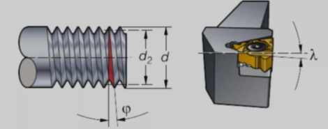
Helical lift angle.
- The helix lift angle depends on the diameter and pitch of the thread.
- The back angle of the tooth side of the insert is adjusted by changing the blade pad.
- The edge tilt angle is γ. The most common edge tilt angle is 1° and corresponds to the standard pad in the toolholder.
Cutting forces during threading in and out.
- The highest axial cutting forces in the threading process occur during the cutting tool plunge into and out of the workpiece.
- Excessive cutting parameters may lead to movement of the insert with unreliable clamping.
Tilting of the blade to obtain clearance.
The blade tilt can be set using a tool pad under the blade in the toolholder. Refer to the chart in the tool catalog to select which pad to use. All toolholders are equipped with a standard pad with a 1° tilt setting.
II. Threaded insert types and clamping solutions
1. Multi-tooth inserts
Advantages.
- Reduced number of tool feeds
- Very high productivity
Disadvantages.
- Requires stable clamping
- Needs sufficient space for retraction after threads are machined
2. Full tooth inserts
Advantages.
- Better control of thread shape
- Less burr
Disadvantages.
- One insert can only cut one pitch
3. V-threaded inserts
Advantages.
Flexibility, same insert can be used for several pitches.
Disadvantages
- Can lead to burr formation and requires deburring.
Clamping solution i-LOCK.
- Extremely rigid threading with inserts in a fixed position
- The insert is positioned in the correct position, guided by the guide rail
- Screws press the insert on the guide back to the radial stop at one of the contact surfaces (red contact surface) in the insert holder
- Reliable insert interface ensures longer tool life and higher thread quality
3. 3 different types of feed methods
The tool feed method can have a significant impact on the threading process. It can affect: cutting control, insert wear, thread quality, and tool life.
1. Improved lateral feed
Most CNC machines are capable of using this method of tool feed through a cyclic program: the
- Chip vs. conventional turning type - easier to shape and guide
- Axial cutting forces reduce the risk of vibration
-Thicker chips, but only contact with one side of the insert
- Less heat transfer to the insert
- Preferred for most threading processes
2. Radial feed
The most common method - the only method available on older non-CNC lathes.
- Produces hard "V" shaped chips
- Uniform insert wear
- Exposure of insert holders to high temperatures, thus limiting depth of feed
- Suitable for fine threads
- Potential for vibration and poor chip control when machining coarse threads
- Preferred for machining hardened materials
3. Alternating feed
- Recommended for large threads
- Even insert wear and maximum tool life when machining very large pitch threads
- Chips are directed in two directions, making them difficult to control
IV. Ways to improve machining results
1. Decreasing depth of cut layer by layer (chip area remains constant)
It is possible to achieve a constant chip area, which is the most commonly used method in CNC programs.
- The first time to go deepest
- Follow the recommended values on the tool feed table in the sample
- More "balanced'' chip area
- The last cut is actually about 0.07mm
2. Constant depth of cut
The depth of cut is equal each time, regardless of the number of passes.
- Higher demands on the insert
- Ensures optimal chip control
- Should not be used when pitch is greater than TP1.5mm or 16TP
Finishing the top of the thread with extra margin.
It is not necessary to turn the stock to the exact diameter prior to machining the threads and use the extra margin/material to finish the top of the threads. For finishing tops, allow 0.03-0.07mm of material from the previous turning process to allow the tops to be properly formed.
Recommended feed values for external threads (ISO metric system).
Ensure workpiece and tool alignment.
Use a maximum centerline deviation of ±0.1 mm. too high a cutting edge position will reduce the back angle and the cutting edge will be cut (cracked); too low a cutting edge position may result in incorrectly shaped threads.
V. Thread turning application techniques for success
1) Check that the workpiece diameter has the correct machining allowance before thread turning, and add 0.14mm as the top of the tooth allowance.
2)Precisely position the tool in the machine.
3) Check the setting of the cutting edge relative to the center diameter.
4) Ensure that the correct insert slot type (A, F or C ) is used.
5) Ensure sufficiently large and uniform clearance (insert-tilt tool pad) by selecting the proper tool pad to obtain the correct tooth side clearance.
6) If threads are not acceptable, check the entire setup including the machine tool.
7) Check the CNC program available for thread turning.
8) Optimize the tool feed method, number of tool travels and dimensions.
9) Ensure the correct cutting speed to meet the application requirements.
10) If the workpiece thread is incorrectly pitched, check that the machine pitch is correct.
11) Before cutting into the workpiece, it is recommended that the tool should start at a minimum distance of 3 times the pitch.
12) High precision coolant can extend tool life and improve chip control.
13) Quick change system ensures easy and fast clamping.
When selecting a tool for a thread turning process, consideration should be given to
- Checking overhang and any clearance required (e.g. shoulders, sub-spindle, etc.)
- Minimize tool overhang for fast clamping
- For less rigid clamping, choose inserts with less cutting force
- High precision coolant for longer tool life and improved cutting control
- Easy coolant connection with plug-and-play coolant lever
- To ensure productivity and tool life, multi-tooth inserts are preferred, with single-edge, full-tooth inserts as the next best choice, and V-tooth inserts as the lowest productivity and shortest tool life option.
Blade wear and tool life.
Tool feed method, optimize the tool feed method, the number and depth of tool travel
Blade tilt to ensure sufficiently large and uniform clearance (blade-tilt pad)
Blade slot pattern, ensuring the correct blade slot pattern is used (A, F or C slot pattern)
Blade material, select the correct material based on material and toughness requirements
Cutting parameters, if necessary, change the cutting speed and number of tool travels
Contact: Jacky Wang
Phone: +86 14714816052
Tel: +86 14714816052
Email: jacky@cncnctools.com
Add: Floor 1, Shixi Industrial area, Canton, Guangdong, China. 510288
 Jacky
Jacky Jacky Wang